In the previous article, I found out there were some mistakes on the PCB of an omni-wheel robot. Here, I present the PCB design modification. My works is supported by PCBWay.
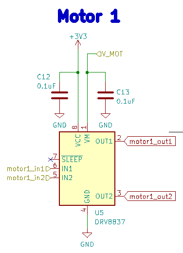
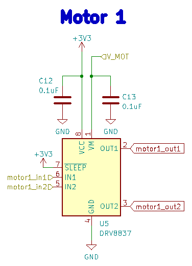
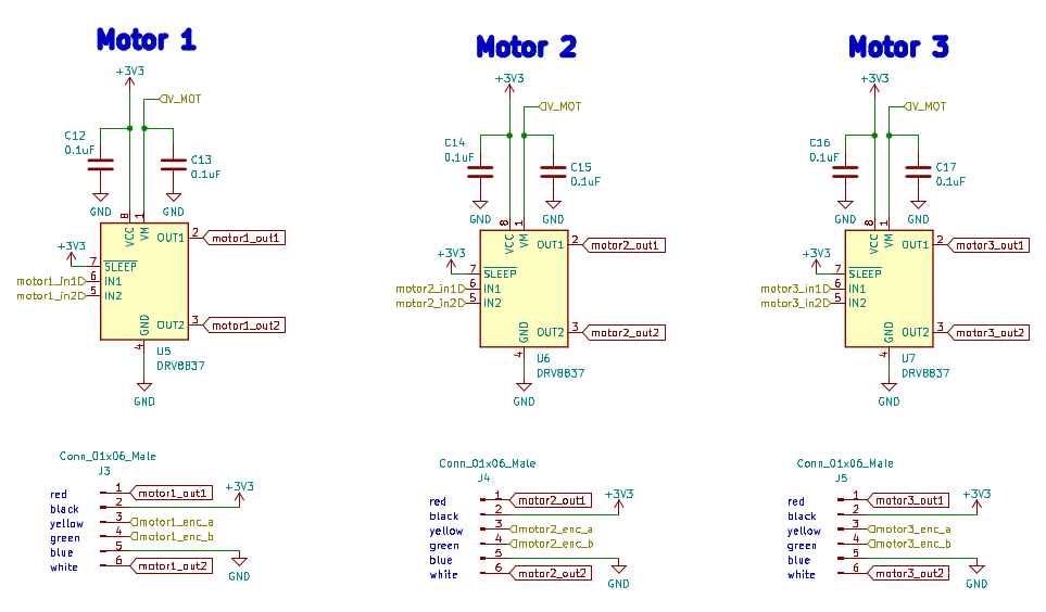
Connect nSLEEP PIN of DRV8837 to HIGH
As the following date sheet shows, I needed to input HIGH to the nSLEEP PIN in order to activate the DRV8837 motor driver.
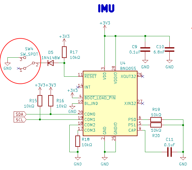
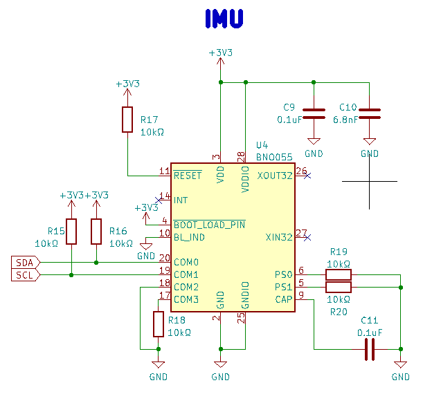
The left-side circuit is the original one and the right-side shows the modified circuit.
Do not use the config mode of IMU
I designed a switch between “config” and “operation” modes in the previous circuit. However, we usually do not use the config mode, so I delete the switch.
Reverse polarity protection (not add this time)
I decided not to add reverse polarity protection because
- The LDO regulator LT1963 (datasheet) has reverse current protection
- The motor driver DRV8837 (datasheet) has overcurrent protection
- Counter-measures for reverse polarity protection cause the voltage drop or need to add a fuse, and we need to replace a fuse when someone misconnects a battery.
There are two major methods to protect reverse polarity. The first one is using schottky diode, and the other is using a P-MOSFET (reference). The latter method results in a smaller voltage drop, but either method results in a voltage drop.
For our usecase, the P-MOSFET should satisfy the following conditions, and ChatGPT recommended AO3401A.
| Item | Conditions should be satisfied |
| Maximum Drain Current | At least 6A |
| On-Resistance | 50mΩ or less (to achieve a forward voltage drop of 0.3V or below) |
| Gate Drive Voltage | Must reliably work at 3.7V (Lipo Battery 1-Cell) |
| Package | 3-Terminal P-MOSFET |
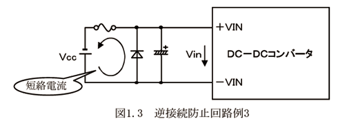
Furthermore, there is a way to add a fuse and a diode in the reverse direction. In this case, we must replace the fuse when someone connects a battery incorrectly.
Widen screw holes
The holes at the center were too small for M3 screws. Thus, I widen them.
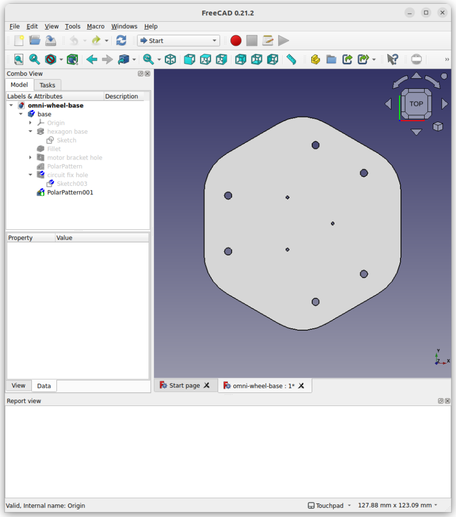
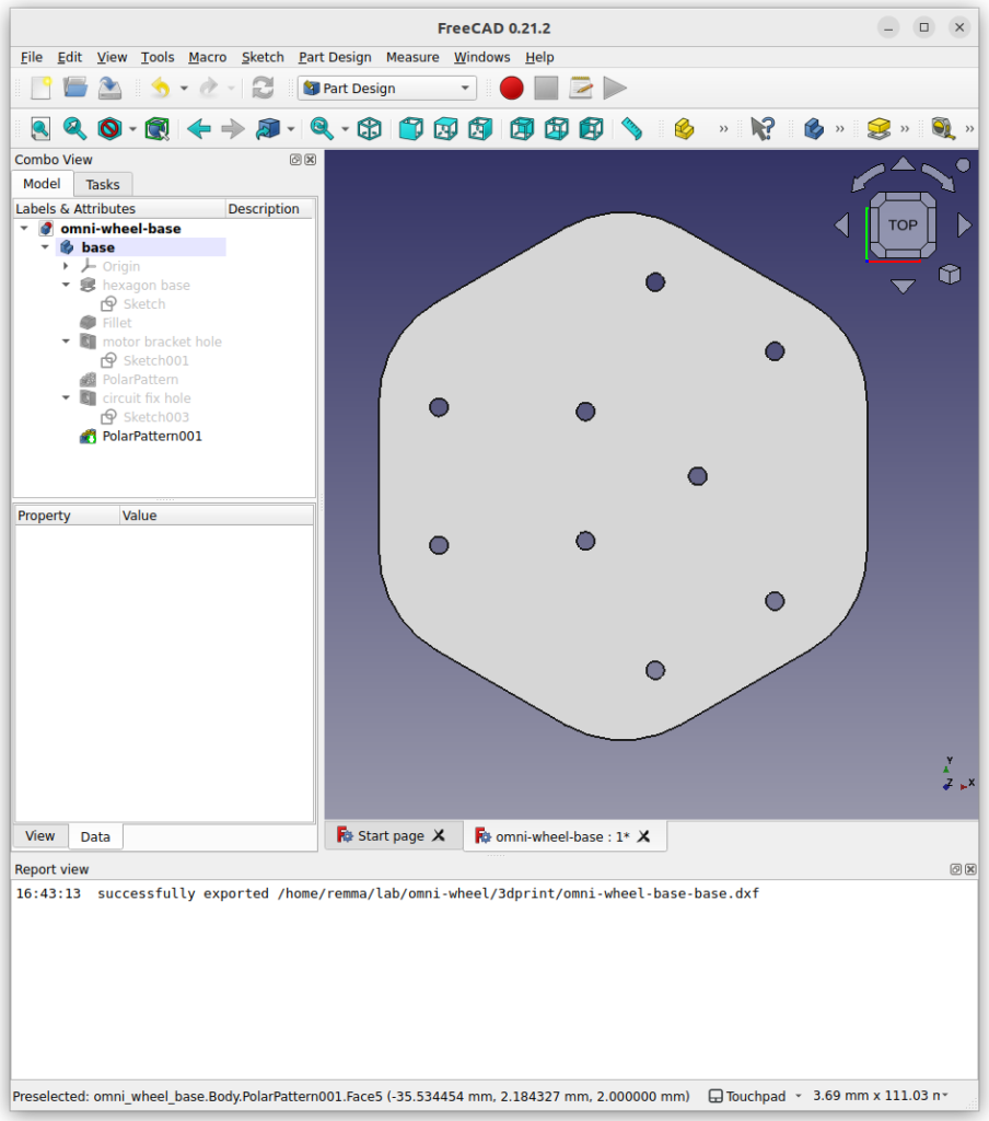
Reverse the motor PIN direction
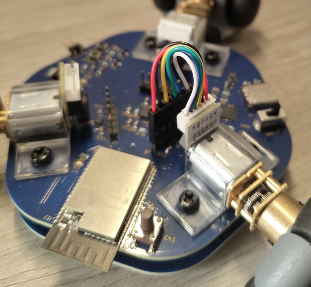
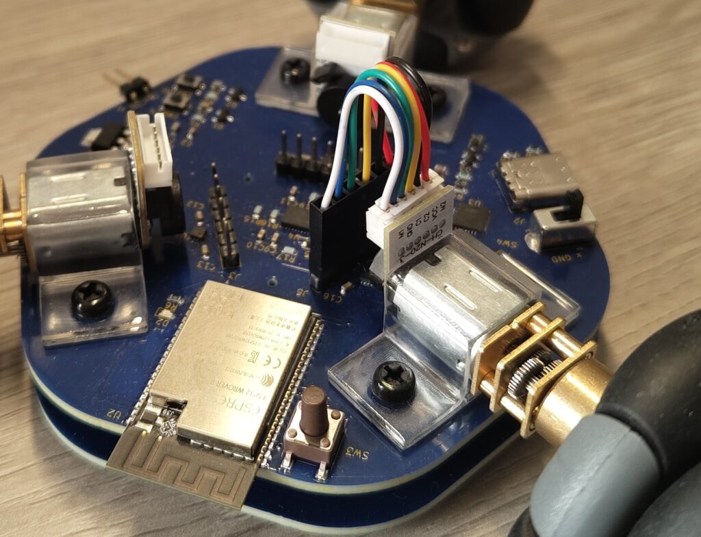
Previously, the cables for motors needed to be twisted because of the PIN direction. I fix the direction by PCB design.
Finalized design
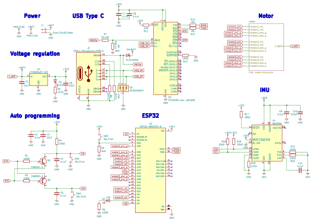
Schematic
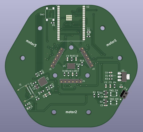
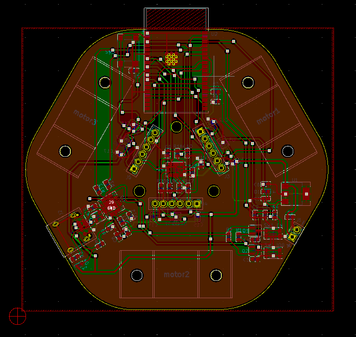
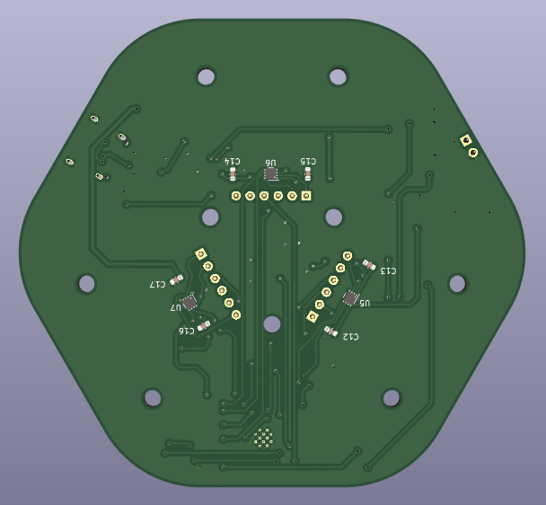
PCB design
I have redesigned the PCB while keeping the following in mind.
- Place components on the PCB to avoid crossing traces.
- Motor drivers are located at the back layer.
- Spaced the components sparsely to make it easier to place vias.
Ordered material
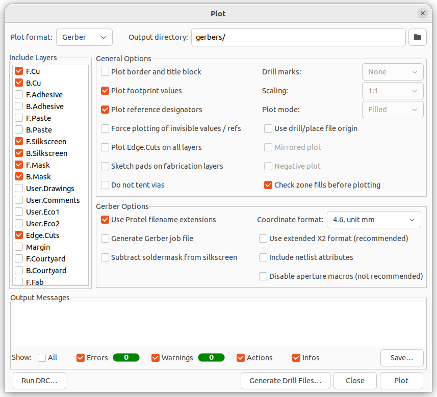
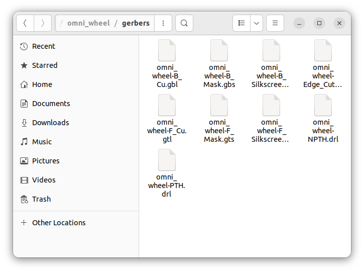
gerbers data
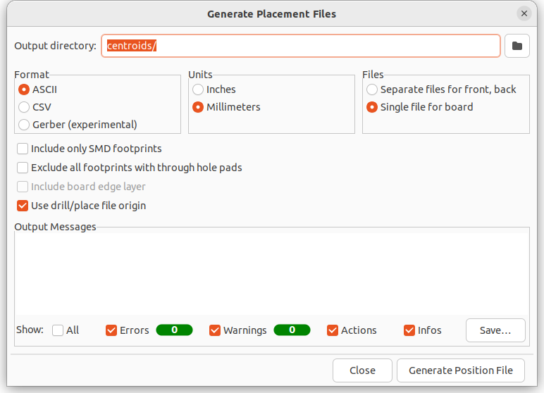
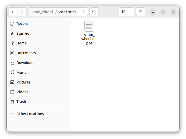
centroids data
BOM
Summary
Wrote an article on PCB design modification. Hope these changes make a robot work.




コメント