In this article, I am going to assemble the omni-wheel robot. The PCB has come from PCBWay. This corporation thankfully sponsors this blog. The schematic design has been done here and the PCB design has been done here. The PCB review from the company was thorough and good. They have been holding a design contest; please check it out here if interested.
Parts
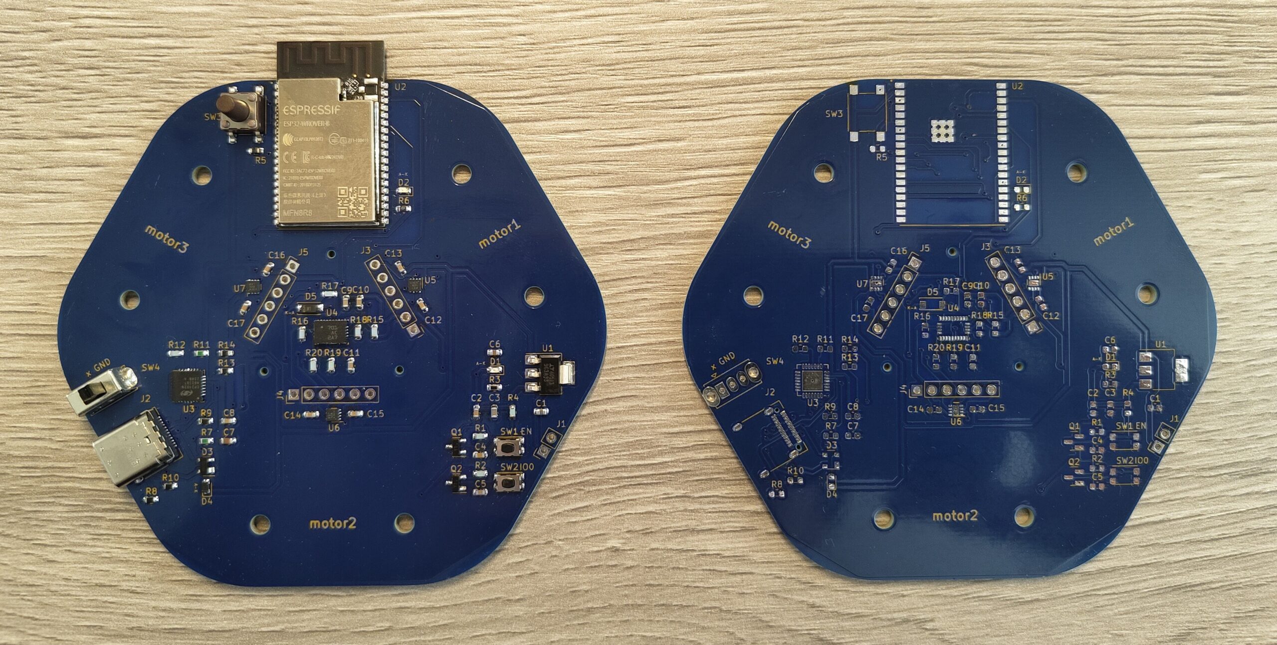
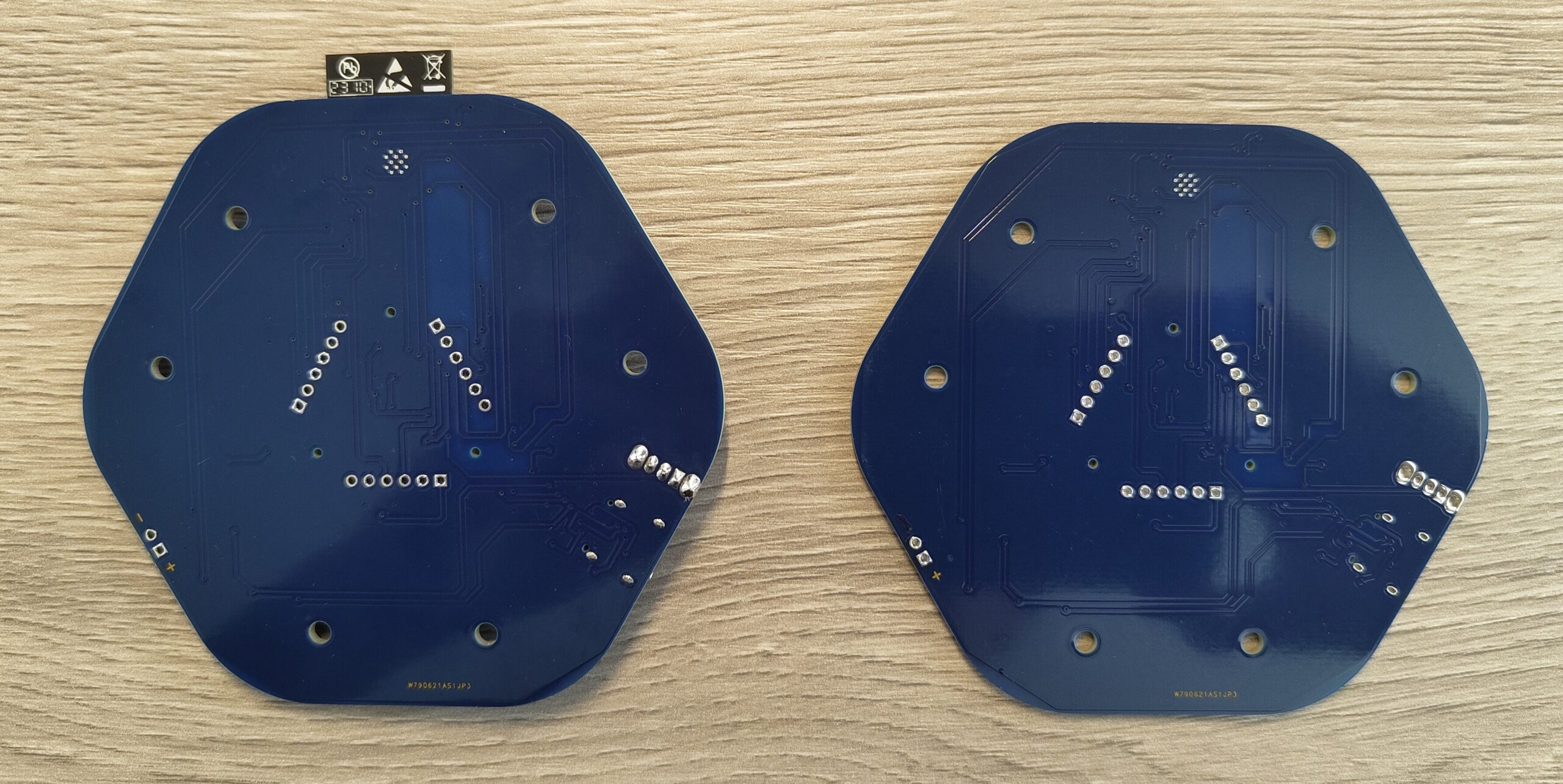
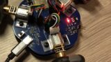
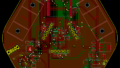
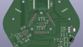
PCB
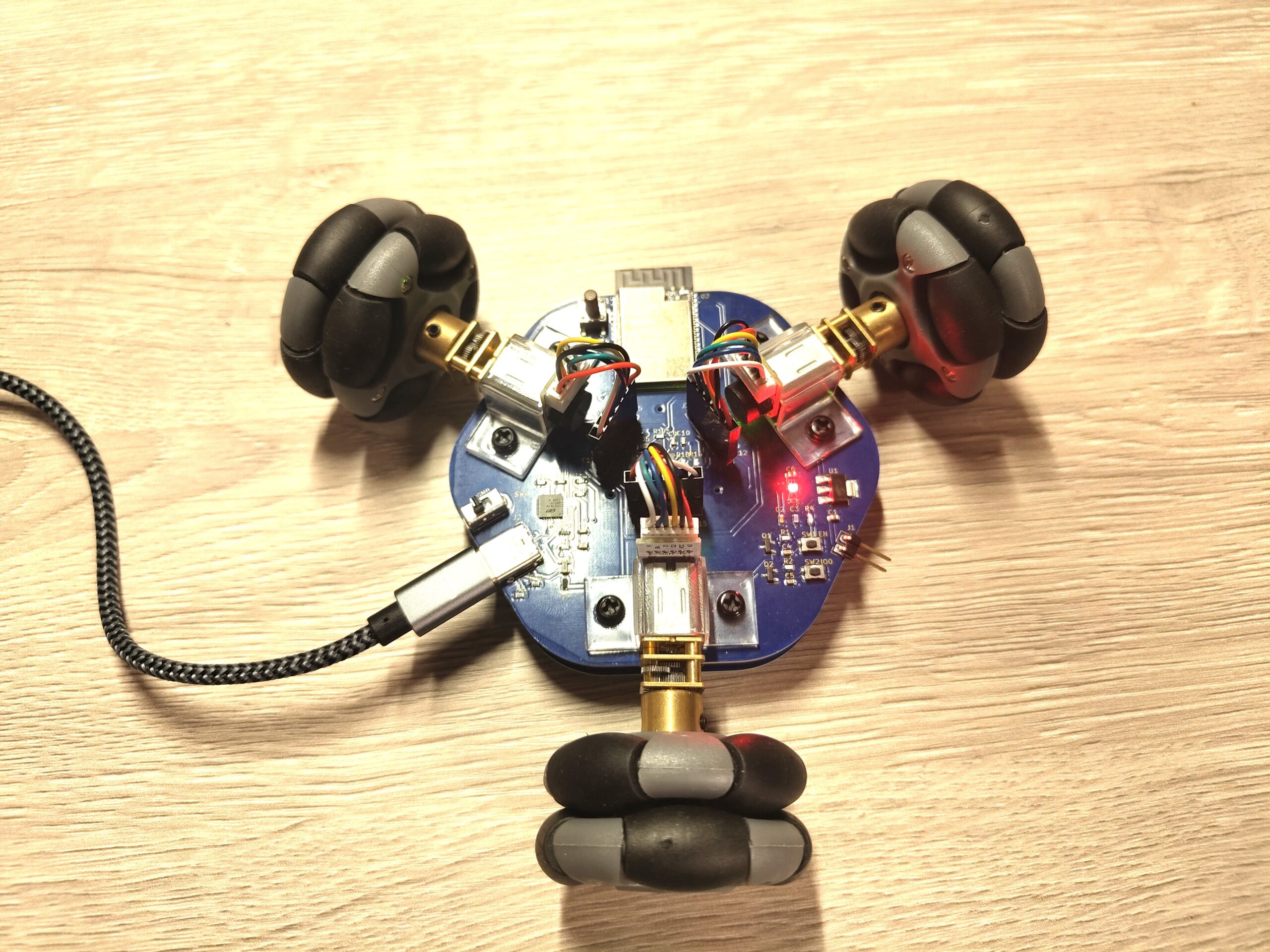
The round shape was good and all the components were soldered well.
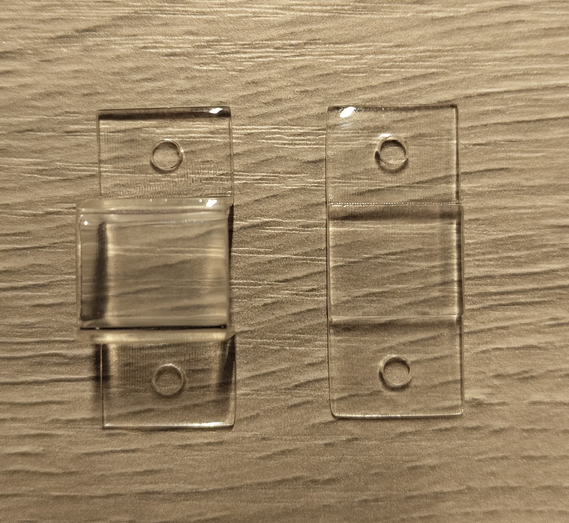
Motor brackets
Those 3D printed parts are coming from DMM.make. I have chosen the transparent parts.
Soldering
I need to solder PINs for the battery and motor connectors.
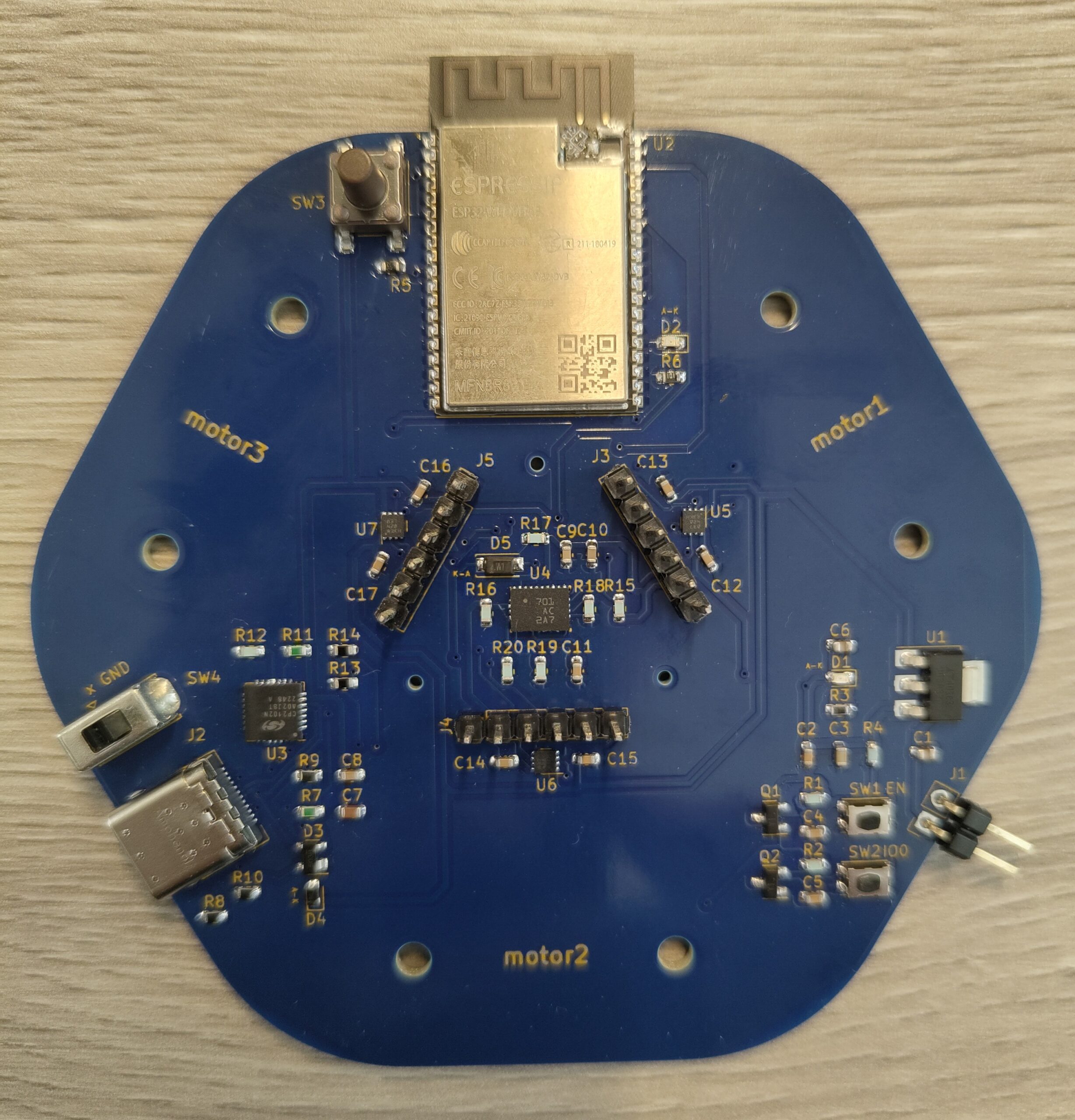
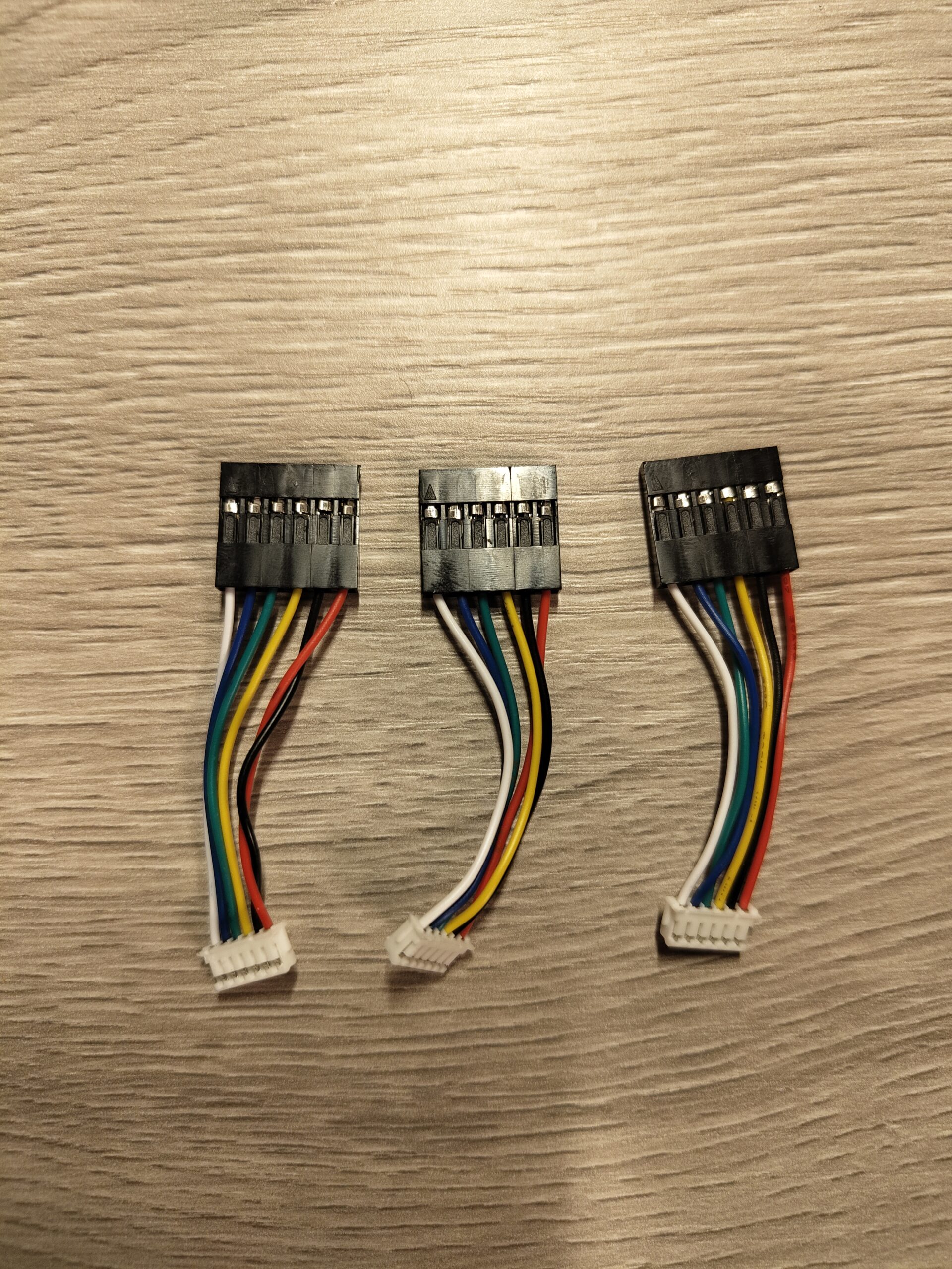
Furthermore, I have prepared harnesses for 3 motors with reference to the following video. For QI connector, use AWG26 for a wire stripper and 1.6 for a crimp tool.
Write software
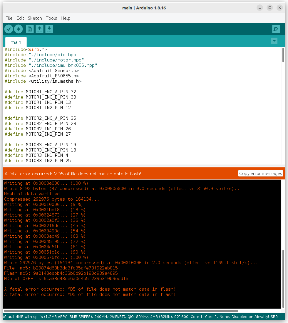
No issue on writing software via Arduino IDE.
Result
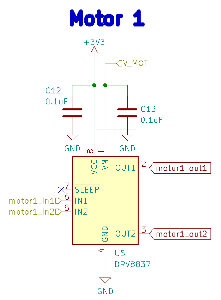
Unfortunately, this time the motors do not function properly. The reason was that nSleep was not connected to HIGH and is internally pulled down. As a result, the device enters low-power sleep mode by default. I am going to connect this PIN to HIGH next time.
Even worse, I have connected +- in the wrong direction to the battery once and the board fails to read imu sensory values after that.. To avoid this happening again, I will add diodes at specific places to protect the circuit from inverse direction current.
Summary
This time, I have failed to make the PCB work properly but am willing to have a design change as soon as possible.
コメント