This article explains the PCB design of an omni-wheel robot. The schematic was designed in the other article.
Design tips
The tips were previously summarized here; we recap some of them below.
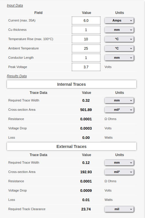
- The maximum current necessary for the motors is less than 6A (= 3 x 2A); the trace width can be less than 0.12mm. The traits other than the power lines consume only less than 0.3A (ref), which requires only 0.01mm traits. We use 0.5mm for traits relevant to the power lines and use 0.25mm for the other traits (Those are quite thicker than the requirement).
- Import the edge.cuts layer design from the dxf file exported by FreeCAD (to be described in detail in the later section).
- Locate the IMU sensor at the center of the PCB.
- Use the GND solid pattern for the front and back sides.
- Secure the space for embedding 3 motors.
- Should use the short power line.
- Should not use vias for the power lines.
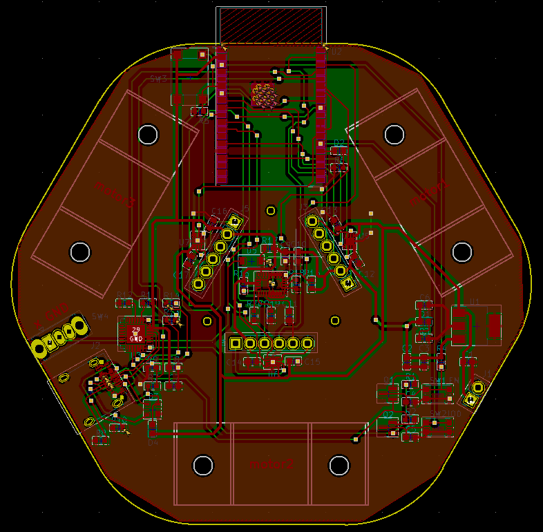
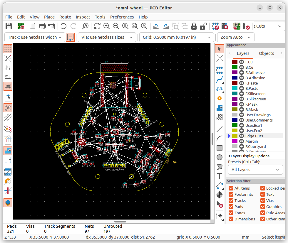
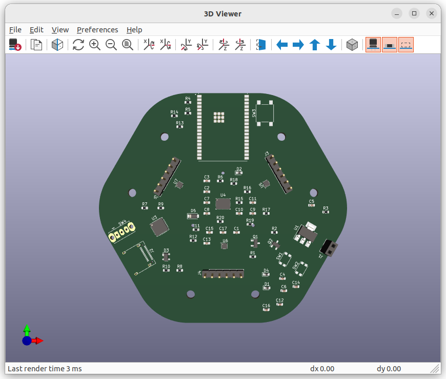
Finally, the following PCB has been designed.

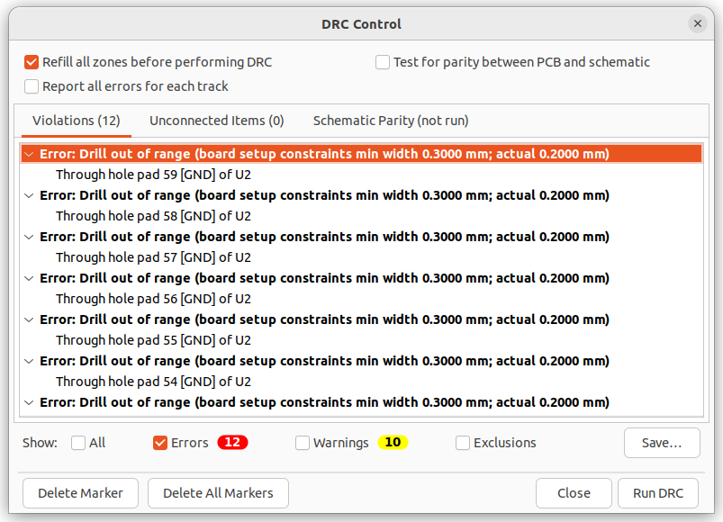
Through the “Design Rules Checker”, these errors were found but I had no problem with the previously designed circuit. Thus, I don’t try any design changes.
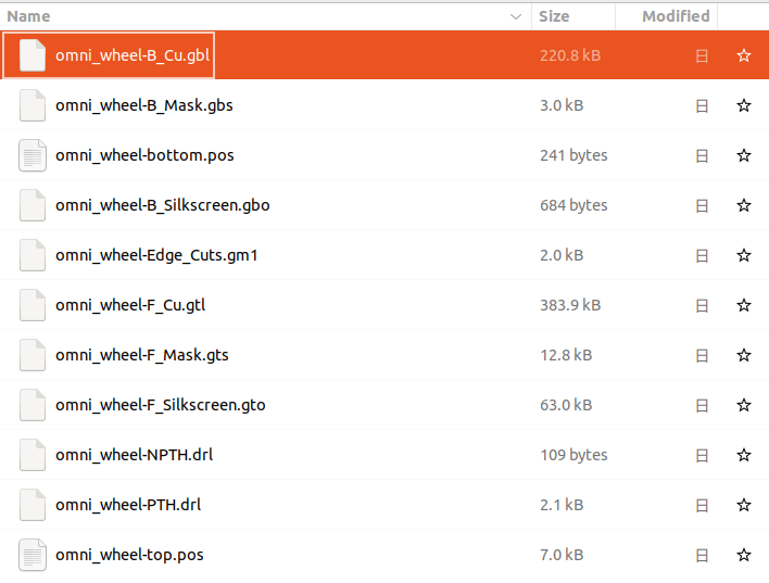
Submit files to PCBWay
The files required for the order are as follows. You can check more details here.
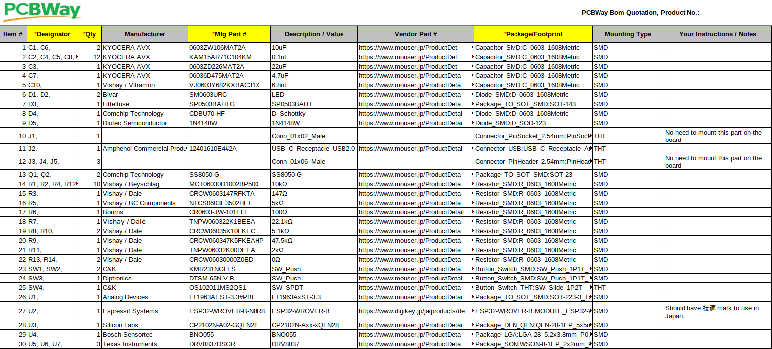
- BOM List
- Gerber file
- Centroid file
I selected 2mm for thickness this time. Other than that, applied the same configuration as before.

Design Edge.cuts layer by FreeCAD
We can import CAD designs by converting the files into .dxf file format (Perplexity).
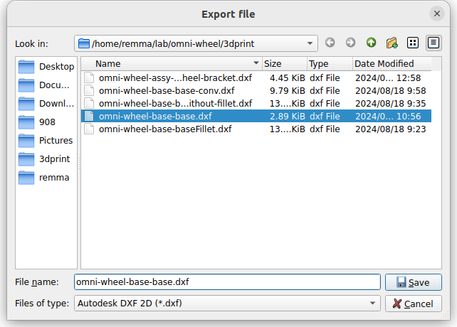
Export dxf file from FreeCAD
- Click File -> Export…
- Select .dxf file format and click Save button
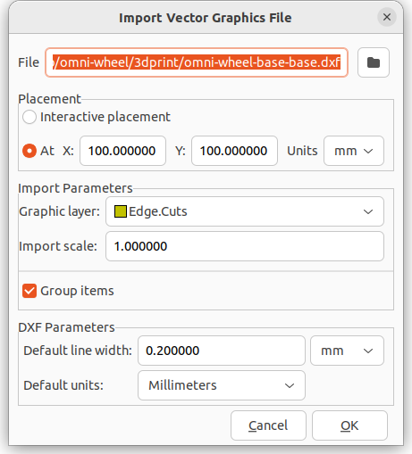
Import dxf file by PCB Editor
- Click File -> Import -> Graphics…
- Select Edge.Cuts on Graphic layer and change the Default units as Millimeters.
Finally, get the drawing on the PCB editor.
Trouble-shooting
When I first tried the above export method, the following error appeared in opening 3D Viewer and KiCad could not show the board outline as expected.
Board outline is missing or malformed. Run DRC for a full analysis.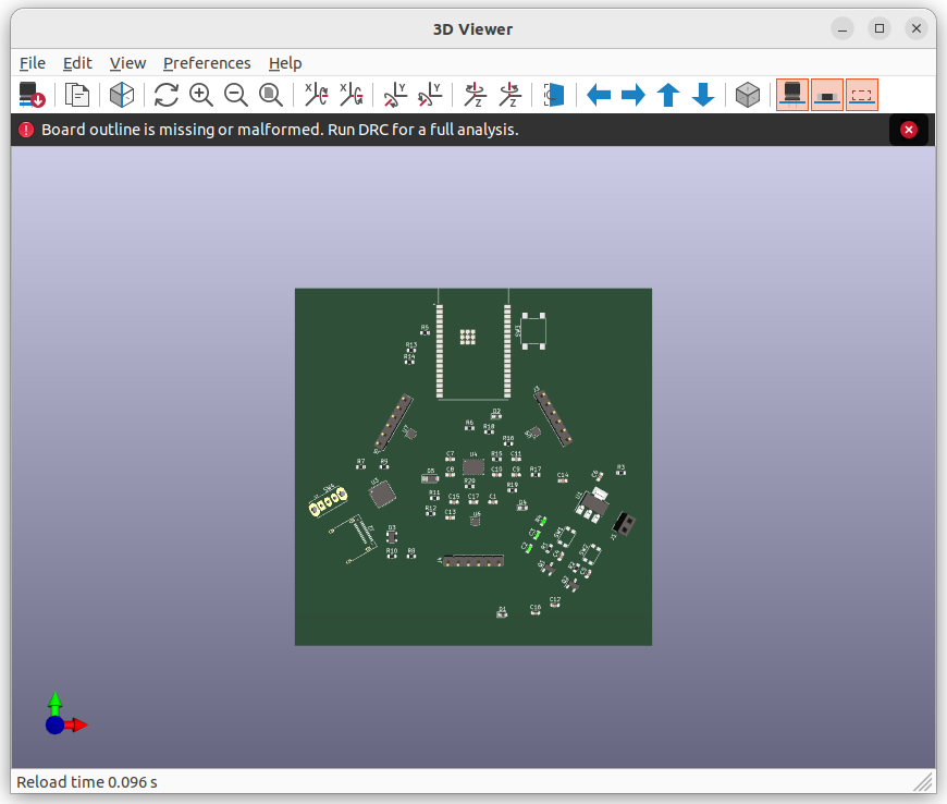
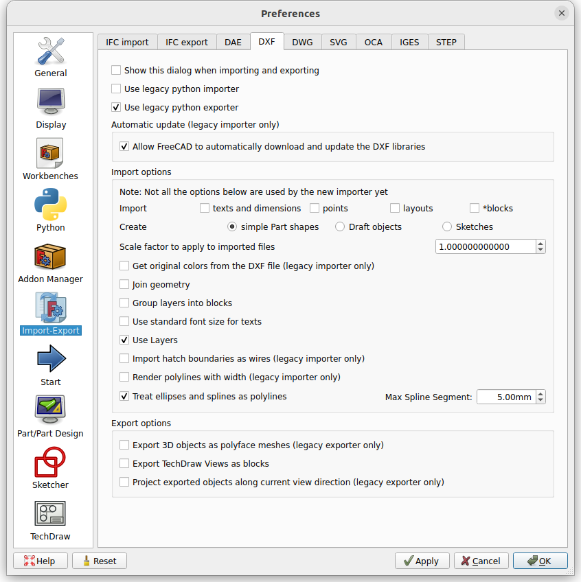
We needed to activate “Use legacy python exporter” in Edit -> Preferences… -> DXF to export a correct dxf file by FreeCAD. This problem has been observed in FreeCAD version 0.21.2 and KiCad version 6.0.2.
Summary
I finished designing an omni-wheel PCB. Was good to know the way to utilize 3D CAD data for the edge cuts layer.

コメント