This article shows the design principle of the body and the motor bracket. Used FreeCAD for the design of the actual parts.
Reference tutorial
- FreeCAD #4 応用講座
- Design A Wall Bracket In FreeCAD – FreeCAD Part Design Tutorial – FreeCAD For Beginners
- FreeCAD How To Assemble Parts
Environment
- Ubuntu 22.04
- FreeCAD 0.21.2
Part design
Motor bracket
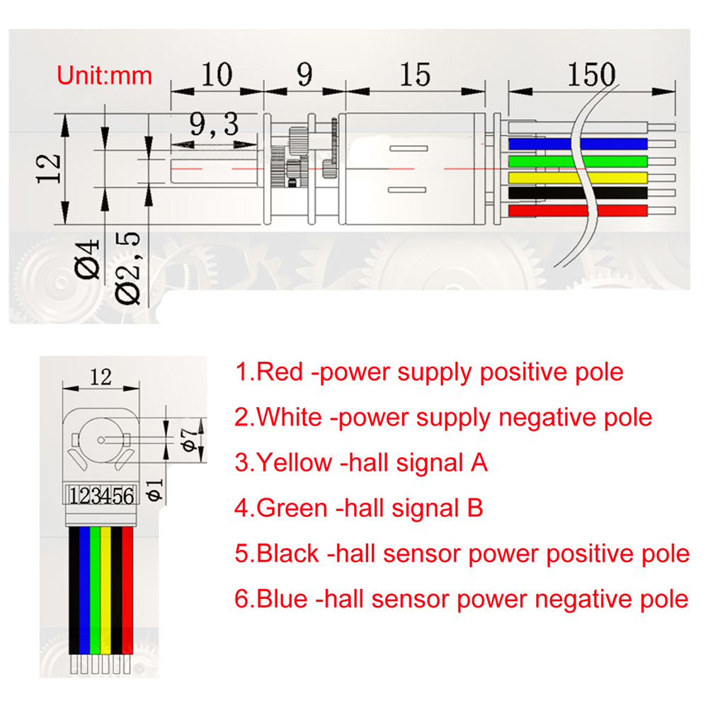
The detailed size of the motor I use can be referred to here.
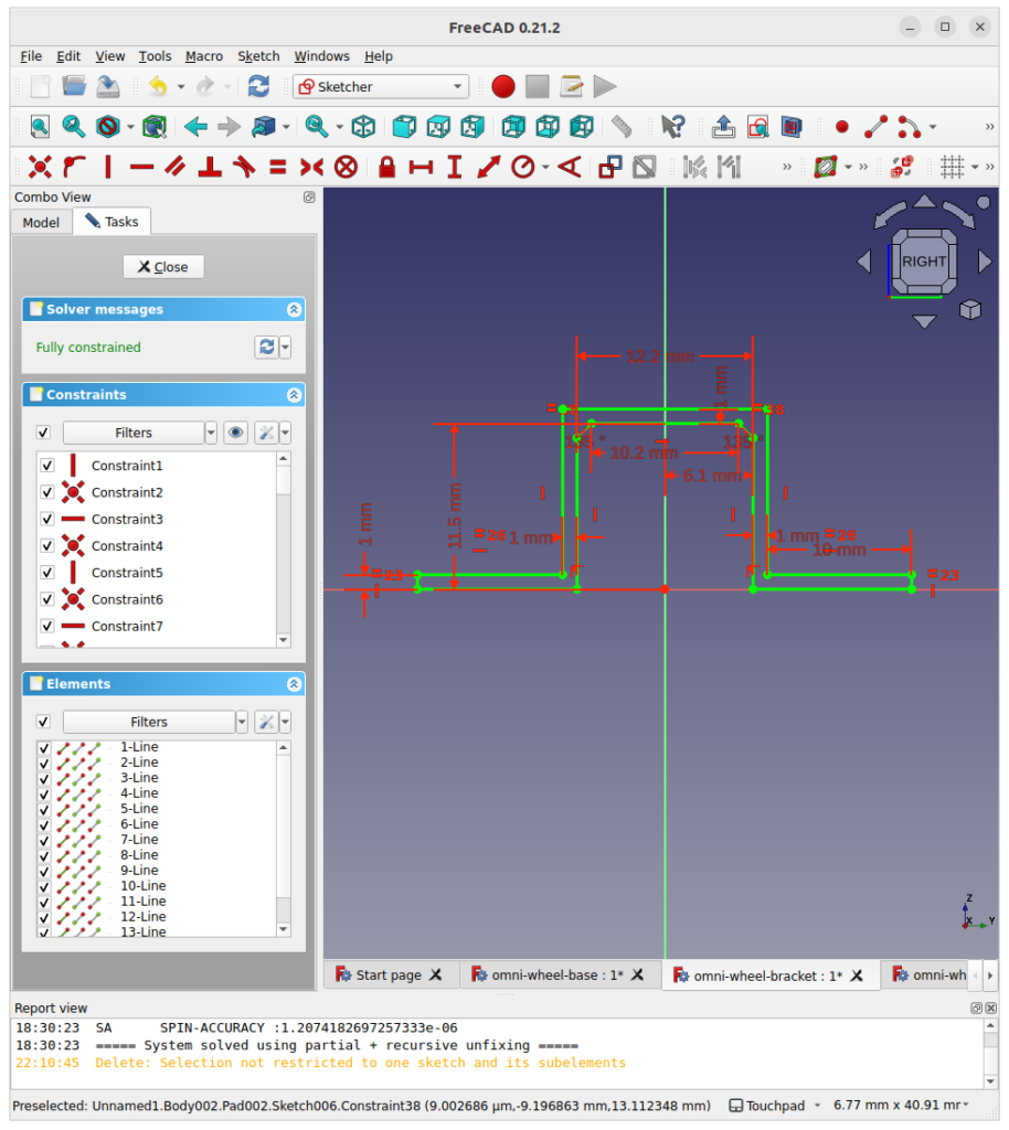
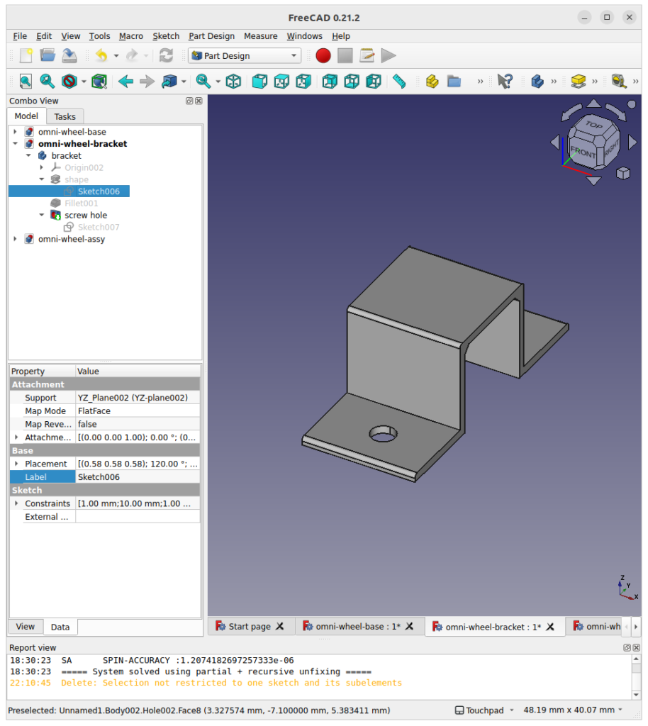
Draw the following on the YZ plane and create a 14.5 mm length pad.
Finally, add the screw hole to put this part onto the omni-wheel robot body.
Body
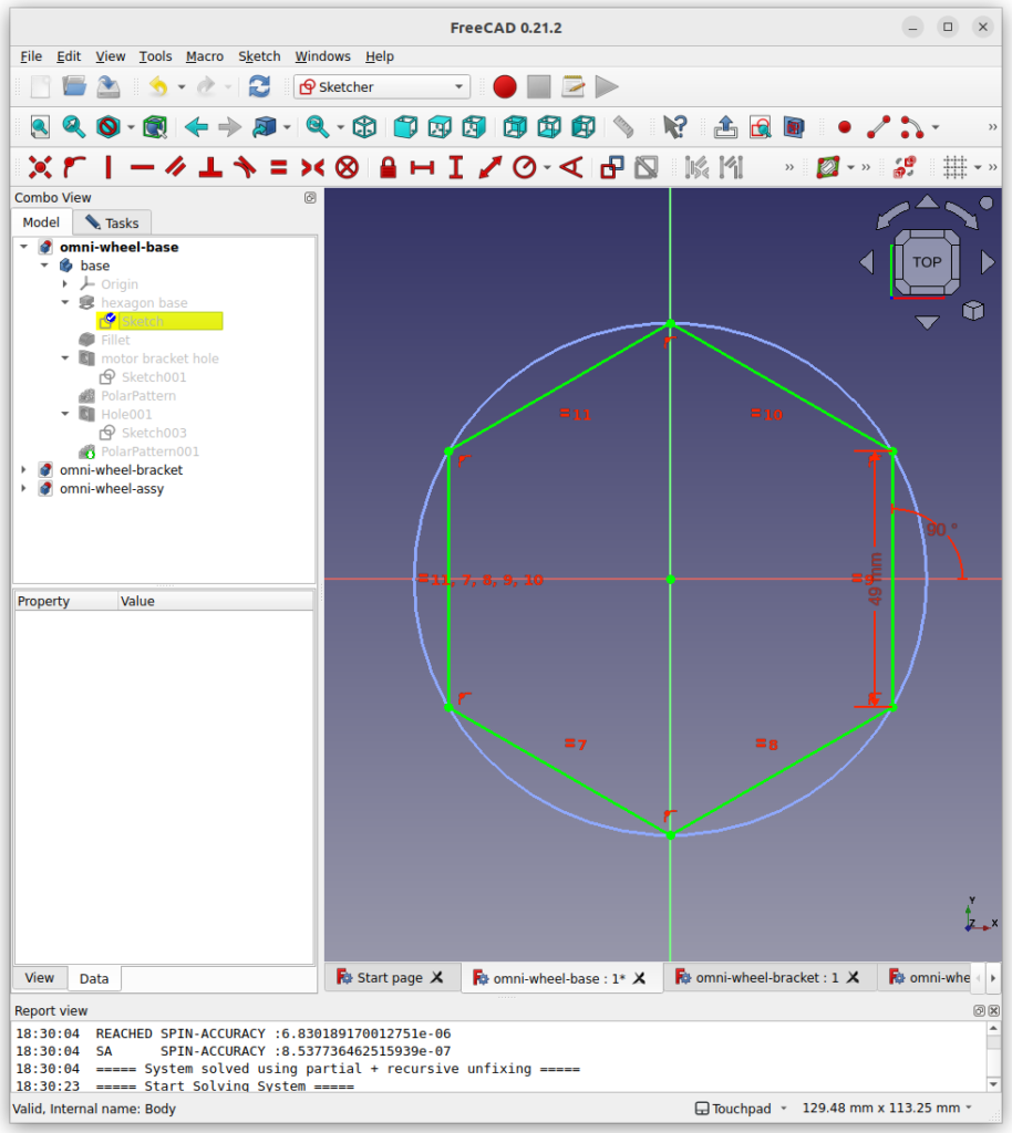
Draw a regular hexagon with a side length of 49mm.
Added fillets for 6-edges. The thickness of this plate is 2 mm.
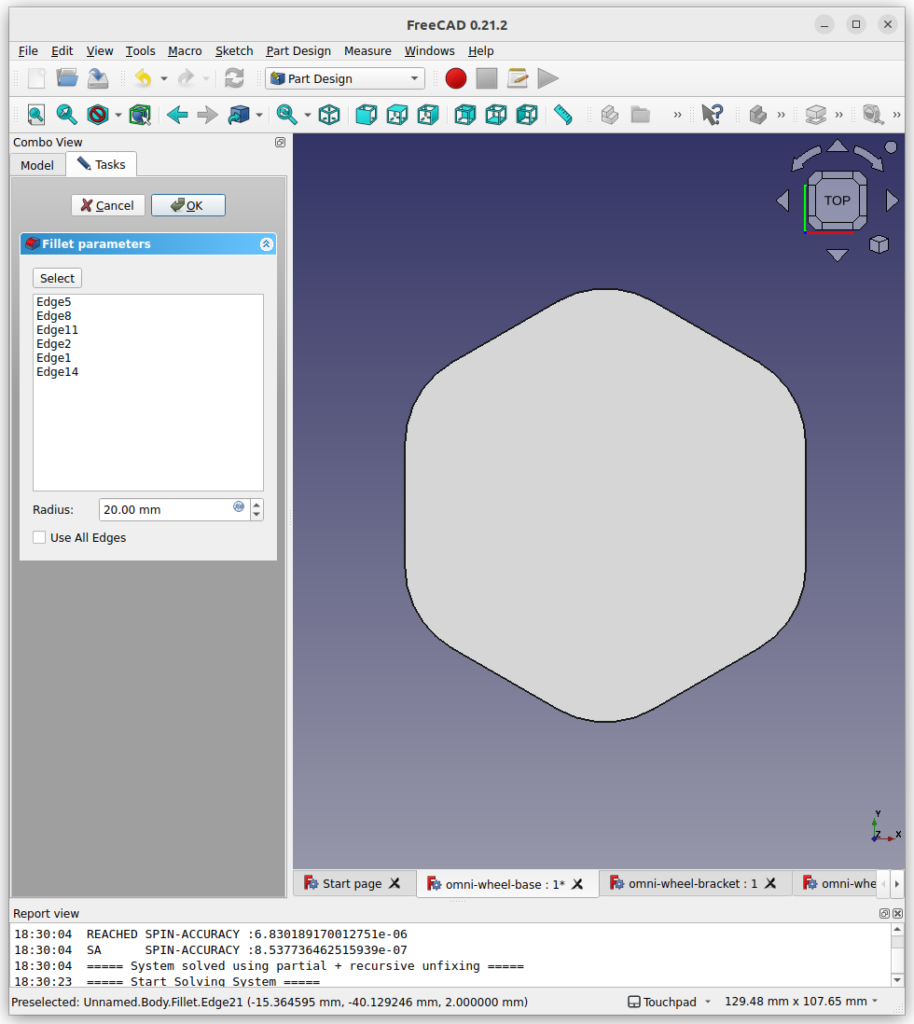
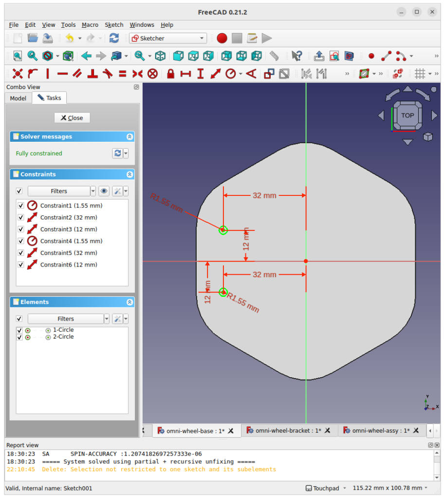
To add motor brackets, add two holes for each bracket.
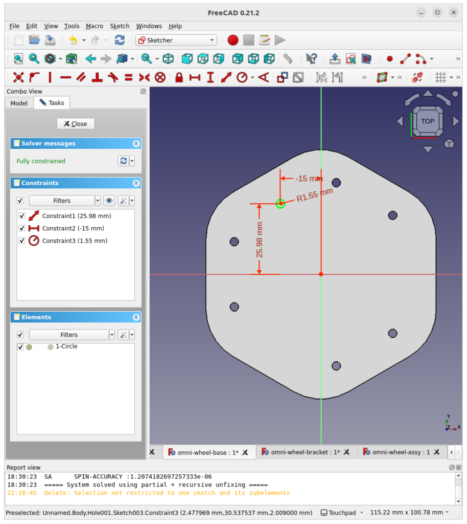
To fix a PCB on the body, add another hole.
Using [PolorPattern], those holes are repeated by 120 degrees.
Assembly
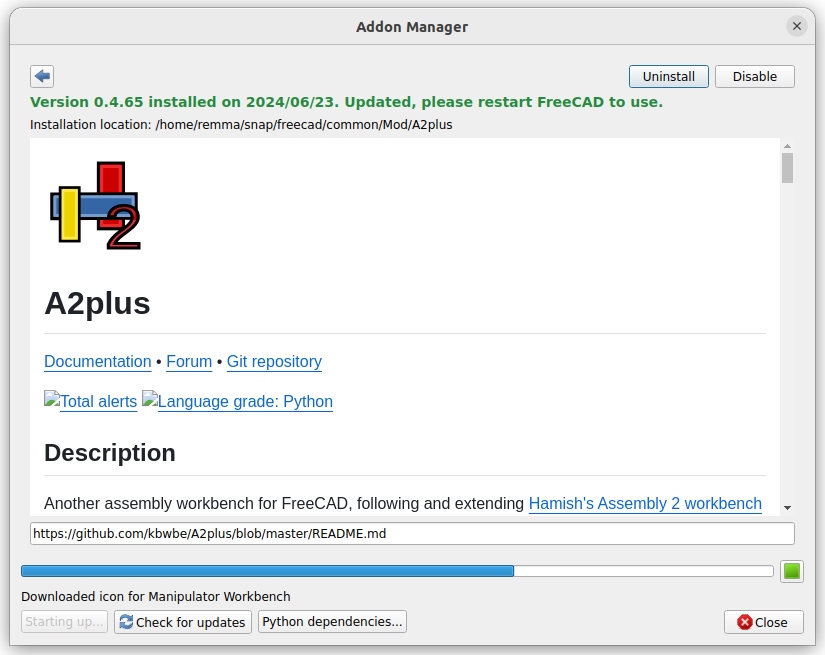
First of all, we need to add plug-in called A2plus. Click [Tools] -> [Addon manager] and install it.
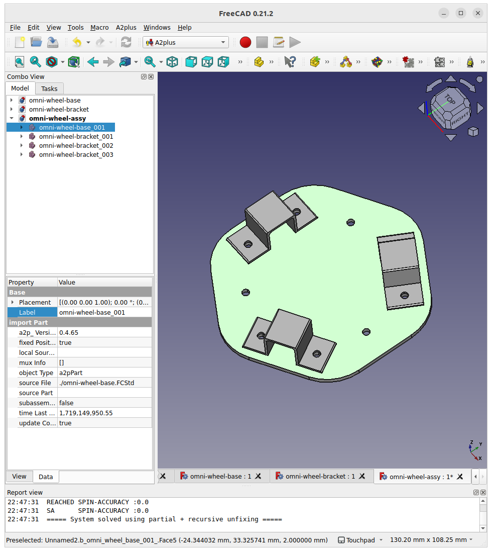
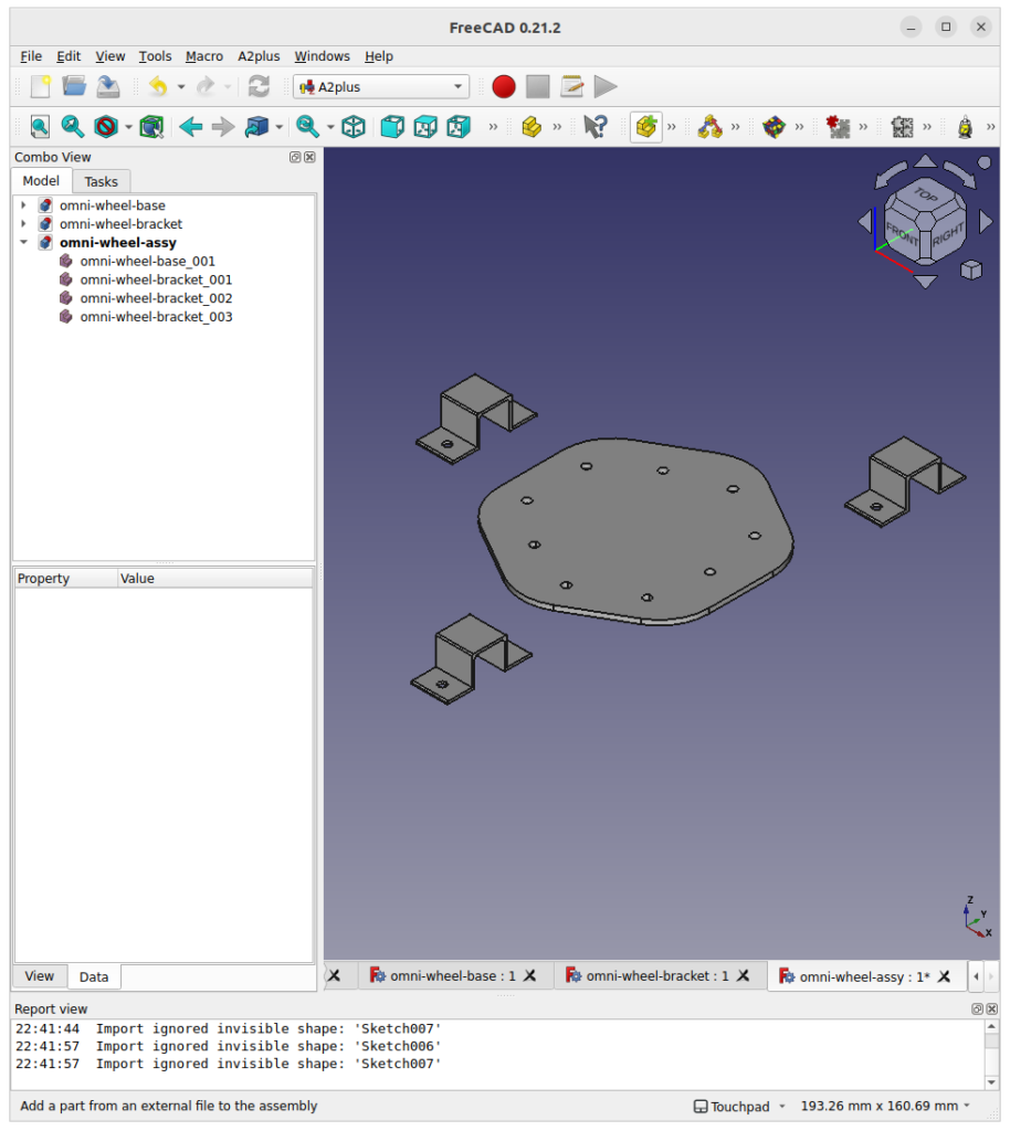
Choose “Add a part from an external file” and add a body and three brackets.
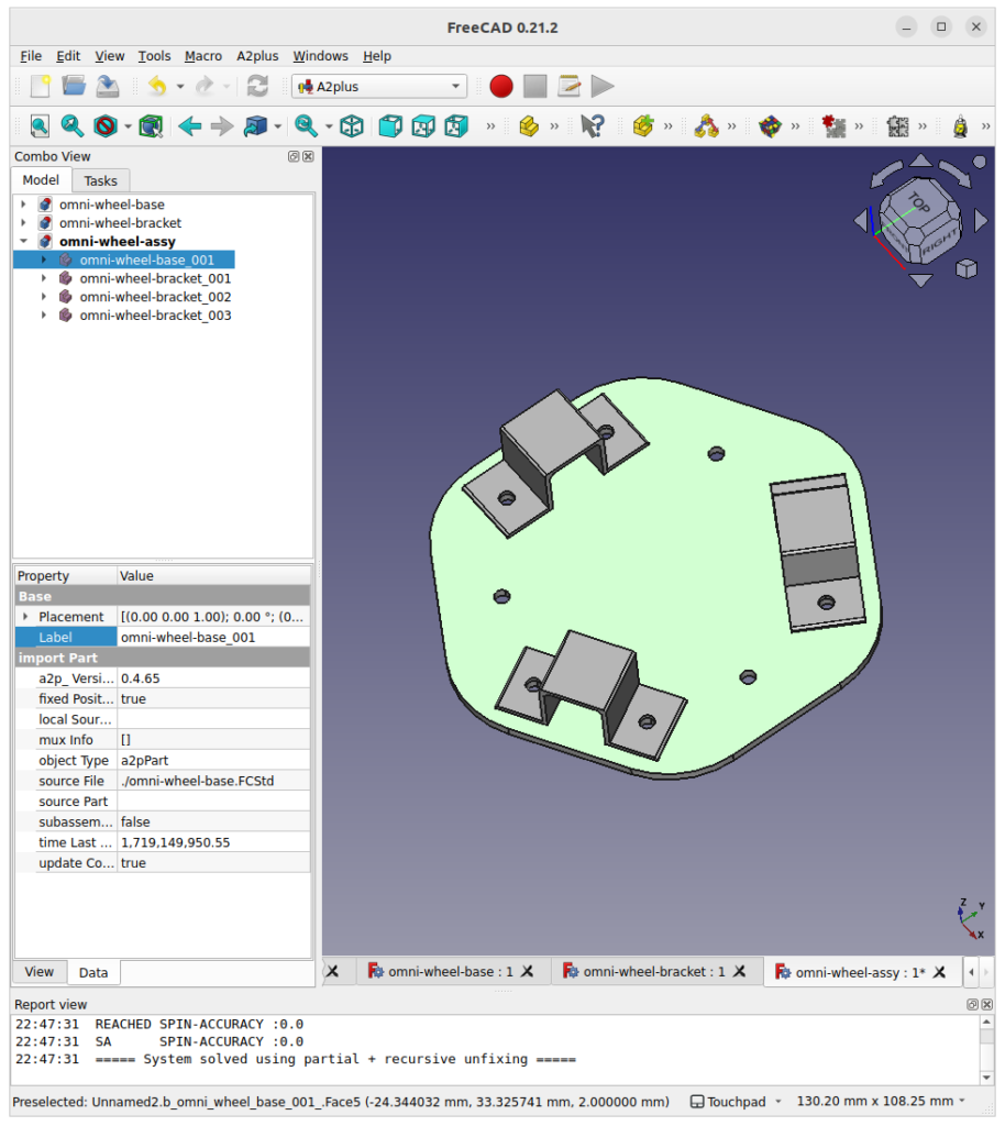
After the following procedure,
- Add AxisCoincident constraint
- Add PlaneCoincident constraint
finally we get the following picture. This gives us an insight into what the body frame looks like.
Tips
Rotate parts from your touchpad
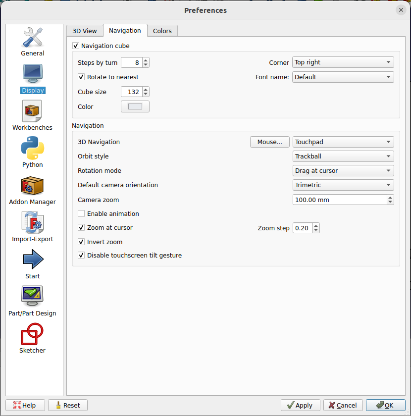
By default, you cannot use your touchpad to rotate the view in FreeCAD. You can choose “Touchpad” in [Edit] -> [Preferences] -> [Display] -> [Navigation] -> [3D Navigation] to utilize the feature. After the configuration, the view can be rotated by a left click while pressing the shift key.


コメント